> At the same time, the cleaning in the water vessel of the original chiller was done.
I attached the photos for the record. [before the cleaning] [after the cleaning]


[Yokozawa, Yuzu]
We performed the TCam photo session at 8:06~8:16 this morning. This time, we took only the ITMX image in the Xarm single bounce.
- ITMX Tcam image: [4/1] --> [4/26]
- horizontal shift = -13.2 pixel = -2.2 mm, vertical shift = +6 pixel = 1.0 mm
- The position of oplev light also shifted at the same time. We guessed the steering mirror in the chamber might have tilted, due to the vacuum evacuation(klog#29307)? I will check the ammount of the shift is consistent or not later
By analyzing the recent TCam images, I identified the mirror center of ETMX, ITMX, and ITMY. When the ETMY or GreenY is ready, we will try to take the ETMY image and identify the mirror center.
Details
- For ETMX, I had an accidental chance to take the TCam for ETMX illuminated by Greenx on 4/23 (during adjustment work of PR2). For ITMX and ITMY, the image was taken on 3/15 (klog#28863).
- Note that the ETMX image was taken after the evacuation an the ITMX and ITMY images were taken before the evacuation.
- ETMX
- fitting result
- overlay with previous reference center (Magenta shows the previous mirror edge and center. Yesllow shows the latest fitting result)
- From this analysis, I updated the fixed radiuss of 1243 pixel which was computed from the conversion factor of 10/113 = 0.0885 [mm/pixel]. This was evaluated from the metal-scale-insert test(klog#28843).
- ITMX
- fitting result
- overlay with previous reference center (Magenta shows the previous mirror edge and center. Yesllow shows the latest fitting result)
- From the metal-scale-insert test(klog#28843), I evaluated the conversion factor as 10/60 = 0.167 [mm/pixel]. Accordingly, the mirror radius could be 660 pixel. But, this estimation has large uncertainty. If one pixel changes in the estimation, the mirror radius changes 600~733 pixel. I decided to use the fixed radius of 630 pixel which we evaluated by hand fitting with Aogaku members previously, because this value has the small uncertainty than the metal-scale-insert test.
- ITMX
- fitting result
- overlay with previous reference center (Magenta shows the previous mirror edge and center. Yesllow shows the latest fitting result)
>The first report some pollution on Tcam mirror in the EYA tank was in February. https://klog.icrr.u-tokyo.ac.jp/osl/?r=28644
This is just a comment. The dust on the TCam mirror in the EYA tank was cleaned on Friday (klog#29213). The mirror could have been cleaned without a complicated cleaning procedure. So, it seems the dirt on the TCam mirror is caused by something other than the oil-ish liquid in the EYA chamber.
[Tomaru, Uchiyama, Takase, Yuzu]
We finished the cleaning of viewports of EY (13:00~15:45).
Details
- At first, Tomaru-san performed the eye inspection for viewports and found four viewports needs the cleaning.
- We replaced the viewport window of TM_out+x-y (reported in klog#29048), put the indium and reinstalled new window.
- We cleaned the three windows (PF_out+x+y, MN_in+x-y, MN_out+x-y).
[Yokozawa, Yuzu]
Related to klog28861 klog28860
Yokozawa-san adjusted the PR3 and SR3 mirrors. We could illuminate the ITMX, ITMY, ETMX, ETMY by Green lasers (not flash).
Except for ETMX, I think I can fit the taken image and update the mirror center. But, for ETMX, the power is not enough to illuminate the mirror. So, it's difficulut to obtain the presice mirror center by my script. (Dan-san's script might work.) If we obtain the GreenX flash or open the GV for EX, the image apperance might change.
I checked the conversion factor between the pixel and the mm, for the two images which I linked in the previous klog. The result looks consistent with past estimations.
Result
I manually fitted the luminous tape on the TCam image using rectangles. (See the attached pdf.) I assumed the tape's width is 1mm.
- ETMX: the width of the rectangle is 113 pixels.
- conversion factor 10/113 = 0.0885 [mm/pixel]
- the estimated mirror radius is 110/(10/113) = 1243 pixel
- ITMX: the width of the rectangle is 60 pixels.
- conversion factor 10/60 = 0.167 [mm/pixel]
- the estimated mirror radius is 110/(10/60)=660 pixel
Comparison with other estimations
For the ETMX and ITMX, we used the fixed factor in the analysis to extract the mirror center, which is 1246 pixels for ETMX and 630 pixels for ITMX.
The conversion factor, which Dan-san estimated independently, is 0.0885 mm/pixel, and the mirror radius is 1243 pixels. These values of the three results look consistent.
This result is just a quick check. I will fix the values after analyzing other images.
[Yokozawa, Yuzu]
We performed the insert of the metal scale by using the jig. Due to the luminouse matelial, the metal scale illuminates. We could take the TCam images to measure the conversion factor from the pixel to the mm, for both EX and IX TCam. The analysis will start soon.
Details


I checked the conversion factor between the pixel and the mm, for the two images which I linked in the previous klog. The result looks consistent with past estimations.
Result
I manually fitted the luminous tape on the TCam image using rectangles. (See the attached pdf.) I assumed the tape's width is 1mm.
- ETMX: the width of the rectangle is 113 pixels.
- conversion factor 10/113 = 0.0885 [mm/pixel]
- the estimated mirror radius is 110/(10/113) = 1243 pixel
- ITMX: the width of the rectangle is 60 pixels.
- conversion factor 10/60 = 0.167 [mm/pixel]
- the estimated mirror radius is 110/(10/60)=660 pixel
Comparison with other estimations
For the ETMX and ITMX, we used the fixed factor in the analysis to extract the mirror center, which is 1246 pixels for ETMX and 630 pixels for ITMX.
The conversion factor, which Dan-san estimated independently, is 0.0885 mm/pixel, and the mirror radius is 1243 pixels. These values of the three results look consistent.
This result is just a quick check. I will fix the values after analyzing other images.
[Yokozawa, Yuzu]
This morning, we took the images by using TCam for the ITMX, and investigated the effect of the air-flow, and the good location to illuminate the mirror.
In our conclusion, (1) the air flow didn't affect the apperance of TCam images (2) the focus of TCam for ITMX is no problem to see the bottom region, which is necessary region to extract the mirror center. We summarized what we are seeing on the image.
Details
- Initially we plan to work in EXC chamber. But, it will be done tomorrow morning.
- Log
- 10:58 open the valuve for the air
- 11:02 open the radiation shield
- 11:06 exit the chamber and close the value for the air
- 11:11 open the valuve for the air
- 11:11~ illuminate the mirror by handy flishlight from +X side (case1)
- 11:18~ illuminate the mirror by handy flishlight from AR side (case2) [11:18~11:23] [11:23~]
- 11:24~ illuminate the mirror by handy flishlight from +X side [Fig]
- 11:31~ illuminate the mirror by handy flishlight from upper side of the ITMX (case3)
- Comparing the image (with airflow) and image (stop airflow), we can't see significant difference. So the hypothesis that the airflow affect the apperance of the TCam image was rejected.
- Figure summarizes the three cases of illuminating the ITMX.
- In case 3, we can reduce the unwanted scatterring light around the coil. When we insert the jig, we will try to illuminate from this direction.
- As can be seen in Figure, the focus of TCam for ITMX is no problem to see the bottom region, which is necessary region to extract the mirror center
- The region around the coil in the upper right is blur. The region around the coil in the upper left (which is difficult to see the coil) is much blur. These region is unnecessary to fit the mirror edge. [Example] I'm not sure why the degrees of blur are different in these regions.
- The taken image looks rotating a bit (roughly 9 degree in my hand fit). This may be due to the rotation of the camera when it was attached.


[Ikeda, Yuzu]
Related to klog28777, klog28792
In this afternoon, we prepated the the metal scale with the luminous tape and took the images of that metal scale in the dark situation as much as possible. The idea of the luminous tape looks working well.
Details
- We setup the TCam test bench between -X side of BS and IYC chamber. The length of the long street is ~ 40m. In addition, we can turn off the light there.
- Fig1 and Fig2 show the prepared the megal scale with the luminous material tape. This is temporal one. ("モ" and alpha means the company name of the tape. Both tapes look fine.)
- We took the images of that metal scale in the dark situation of the center area by turning off the lights.
- The taken image are
- In my quick check, the image shows blur around the edge of the tape. But, I think that's not critical to evaluate the conversion factor.
- When we analyze the image, we will read the number of pixels between bright tapes, measure the distance of tapes, and can compute the conversion factor between pixel and length in mm unit.


[Ikeda, Yuzu]
After the work of klog28812, we investigated the depth of field of TCam (test bench), that is how long the TCam can take the focused image in the length direction.
To do that, we checked the image of the 1m metal scale. The schematic view is shown in Fig1. In the Fig1, `z` is the length of the metal scale that is in focus. In our rough check, the depth of filed in length direction (which is `x` in Fig1) was +/- 15 cm.
When I analyzed the image in the Hokubu-kaikan, I realized I faield to take the image... I will show the result next chance.

[Yokozawa, Yuzu]
We investigated the way to illuminate the ITMX from IXA chamber. In short, it's not easy to illuminate the mirror from the IXA chamber whose distance is about 20m away from ITMX.
Details
- When I illuminated the mirror by the flashlight (similar to this), the taken image shows the light reflected by many places. [example]
- We can't see the mirror edge clearly. This way is unsuitable to illuminate the metal scale.
- When I illuminated the mirror by the directional flashlight, we can't see the mirror edge in the taken image. [example]
- The possible reasons are (1) the power of the flashlight is not enough. (2) the light did not reach the mirror well because the flashlight was supported by the hand.
[Ushiba, Yokozawa, Yuzu]
In this morning, Ushiba-san tried to demonstrate to insert the metal scale by the jig (klog28764) in front of the ETMX. We found it's difficult to take the image to pick up the value of the metal scale when we illuminate the metal scale from the inside of the EXC chamber. We need to find the way to illuminate the metale scale.
- Fig1 shows the size of the prepared jig. The height between the floor and the cross point is 140 mm. The other size can be adjusted by changing the cramp point of the lab jack.
- Fig2 shows the Ushiba-san's working scene.
- After inserting the metal scale, we tried to take images by changing the exposure time and chaning the illuminating point by handy light. The gain was fixed to be 570.
- We are considering solusions:
- to illuminate the mirror from EXA chamber by handy light.
- to use the luminous staff instead of illuminating by handy light.
- I checked the image of ETMY taken at 2022/04/25 with the metal scale [Figure of ETMY]. The exposure time is 2 s. But, the situation of this ETMY and today's ETMX is not same, such as the installed WAB.


Related to klog28486.
I made a few changes to the telescope configuration. As a result, I was able to take in-focus images with two kinds of cameras at the same time (Fig1, Fig3).
- New configuration (Fig2). I added the T2 extension tube of 7 mm length. In my computation, the extension length should be 6 mm. But it didn't match. After several attempts, I found 7mm is suitable.
- As seen in Fig2, the difference in the optical lengths is not precisely 7mm.
- As shown in Fig1, the image taken by gige camera is flipped. I couldn't find the option to flip in the application.
- I will analyze the taken images and investigate whether the centers of the images are aligned or not, after rotating the images.
- In the previous images, the centers of the images are shifted due to the adapter (klog28647).


[Yokozawa, Yuzu]
Related to https://klog.icrr.u-tokyo.ac.jp/osl/?r=28676.
We constructed the special jig to insert the metal scale in front of the ETMX and ITMX. Figure 1 shows the overall picture of the jig. The adapter to hold a metal scale is attached to the end of the jig (Fig2).


[Yokozawa, Yuzu]
Just before closing the chamber, we plan to measure the conversion factor of the image pixel of TCam and the actual length [mm]. Concretely, we ask Ushiba-san to insert the metal scale in front of the mirror, by using the special jig.
Today, we investigate the room size beside the ITMX and WAB in the IXC chamber. Based on the measured size and the fruitful input by Tomaru-san, we will prepare the jig.
The same process will be done for the ETMX.
Measured values
- horizontal distance between the ITMX and WAB: ~ 2 cm
- height of ITMX from the table: ~10 cm
- height to insert the metal scale: 10 cm; we plan to elevate the jig by lab jack to the height of 17 cm
- horizontal distance between the bottom of the ITMX and the place to put the jig: ~20cm

[Ikeda, Yuzu]
We discussed this result. In our consideration, the reason why the image was off-center was that the camera adaptor for the ASI camera was not held tightly in place. Perhaps a shift of the image sensor is an incorrect extrapolation. I will reconsider the setup for the TCam test bench.
- In the four corners of the image taken by the gige camera, there are vignetting (in Japanese, called Kerare) (Fig1). The area size of these Kerare looks almost same size. So, the sensor of the gige camera should be no problem. So, we doubted something happened in the ASI camera side.
- Fig2 shows the adapter to hold the ASI camera (left black one). Right red one is the ASI camera. This adapter can be loose in some cases.
- Fig3 shows the inner part of the adapter. Two screws tighten the camera. As seen in this figure, when I tighteded only one screw, the camera will be shifted to one way. We suspenct this happened in the previous operation test. In quick calculation, the 0.5 mm off-center of the image sensor can explain the previous off-centered images. I will reconsider the setup for the TCam test bench.
- Note that from the visual inspection by Ikeda-san, the image sensor of the ASI camera is well centered in the camera. The 0.5 mm shift of the image sensor was not obserbed.


[Yokozawa, Yuzu]
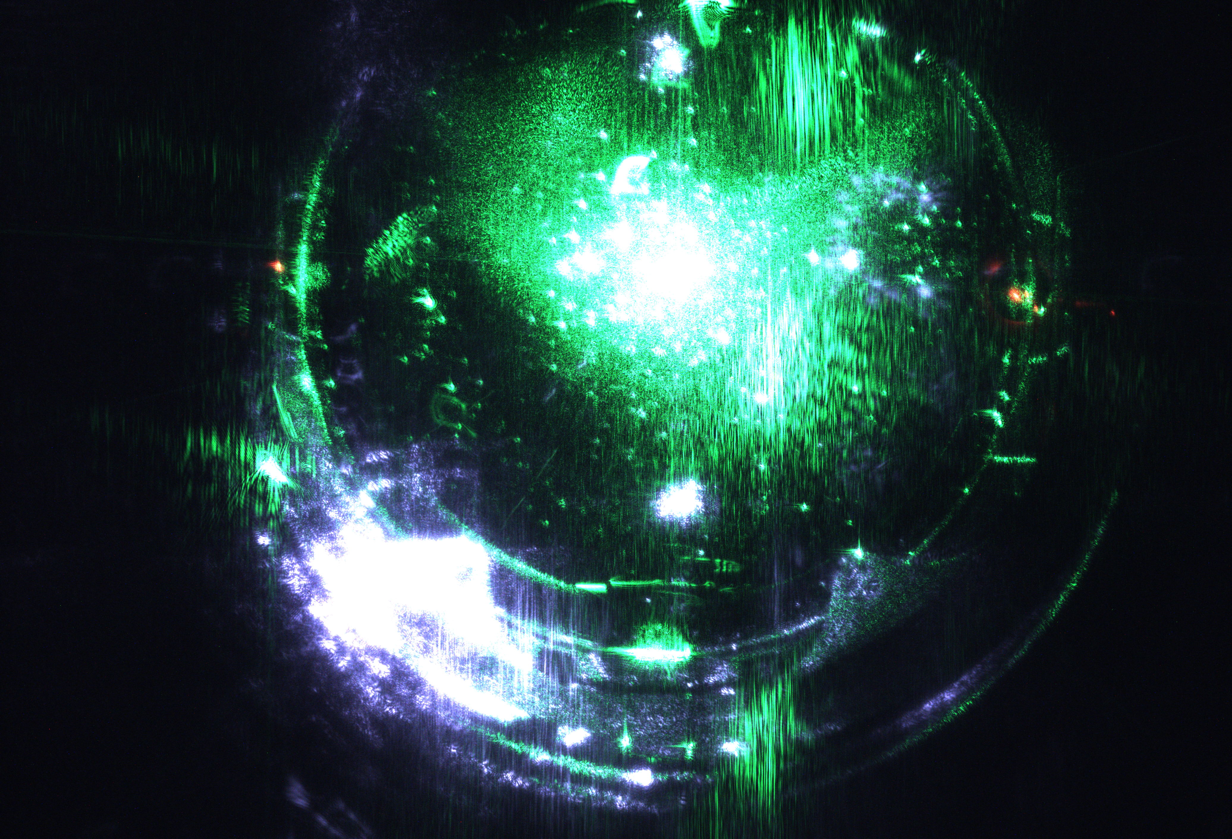
As an irregular maintenance of TCam for ETMY, we performed the visual inspection this afternoon. During O4a and the commissioning period, the TCam for ETMX showed a problem with the beam appearance (Fig1). We suspected it was due to the problem with the mirror surface in the TCam system or the objective lens of the telescope. For example, it could be moldy. We compared the conditions between TCam of ETMX and ETMY.
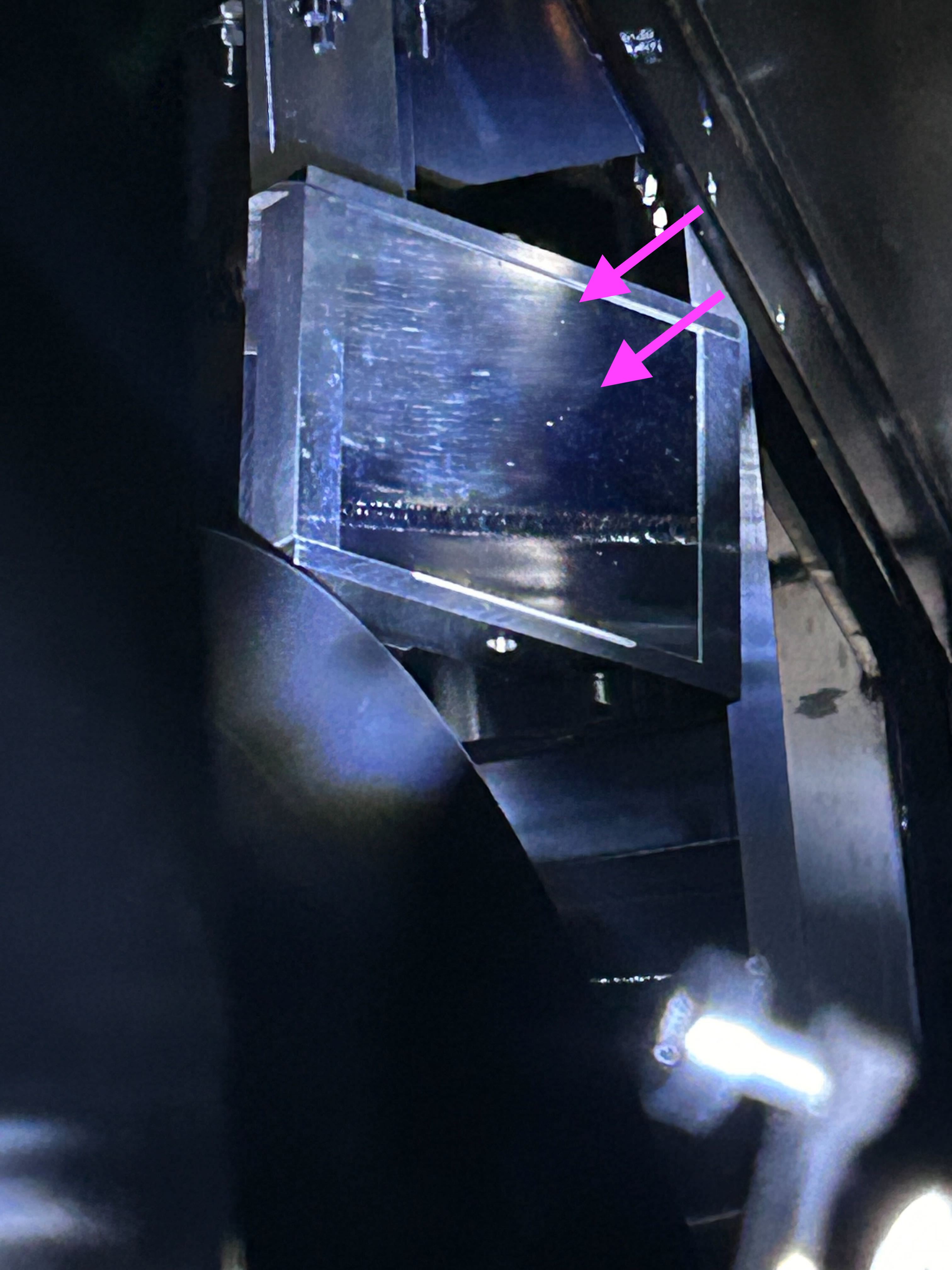
- We opened one of the side walls of the TCam (Fig2). However, the mirror in front of the telescope blocked to see the surface objective lens.
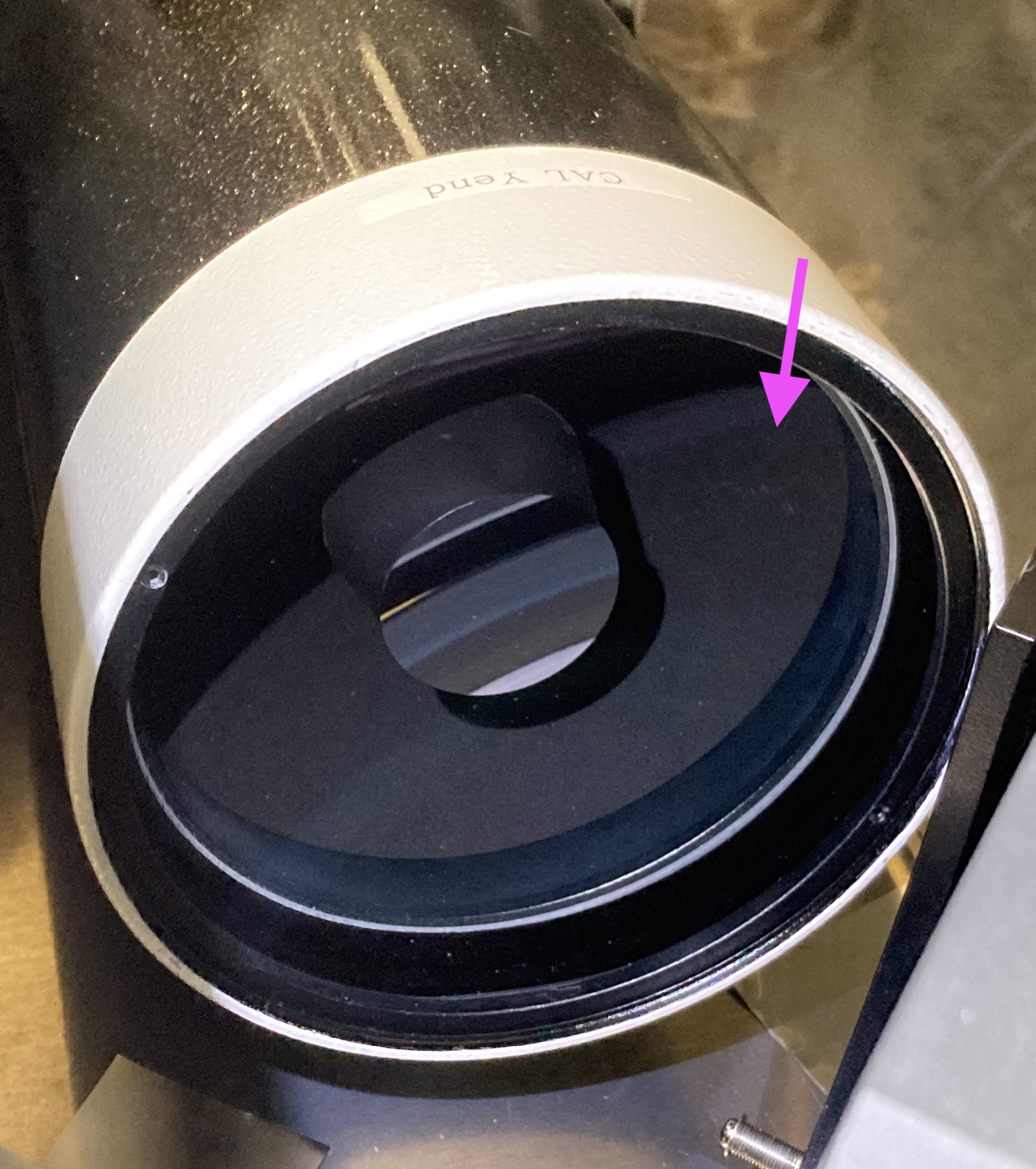
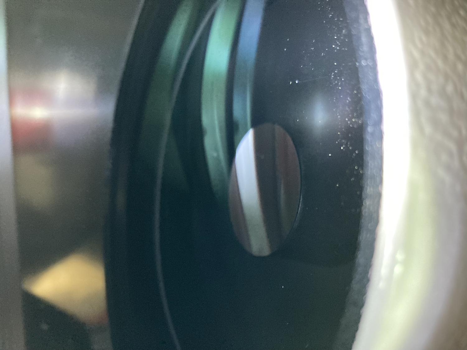
- Next, we opened the top side wall and checked the surface objective lens. We noticed that the surface of the objective lens was found to be contaminated (Fig3). It does not appear to be an obvious mold, but I am not sure what it is. We want to clean it next time with ethanol and a cotton swab.
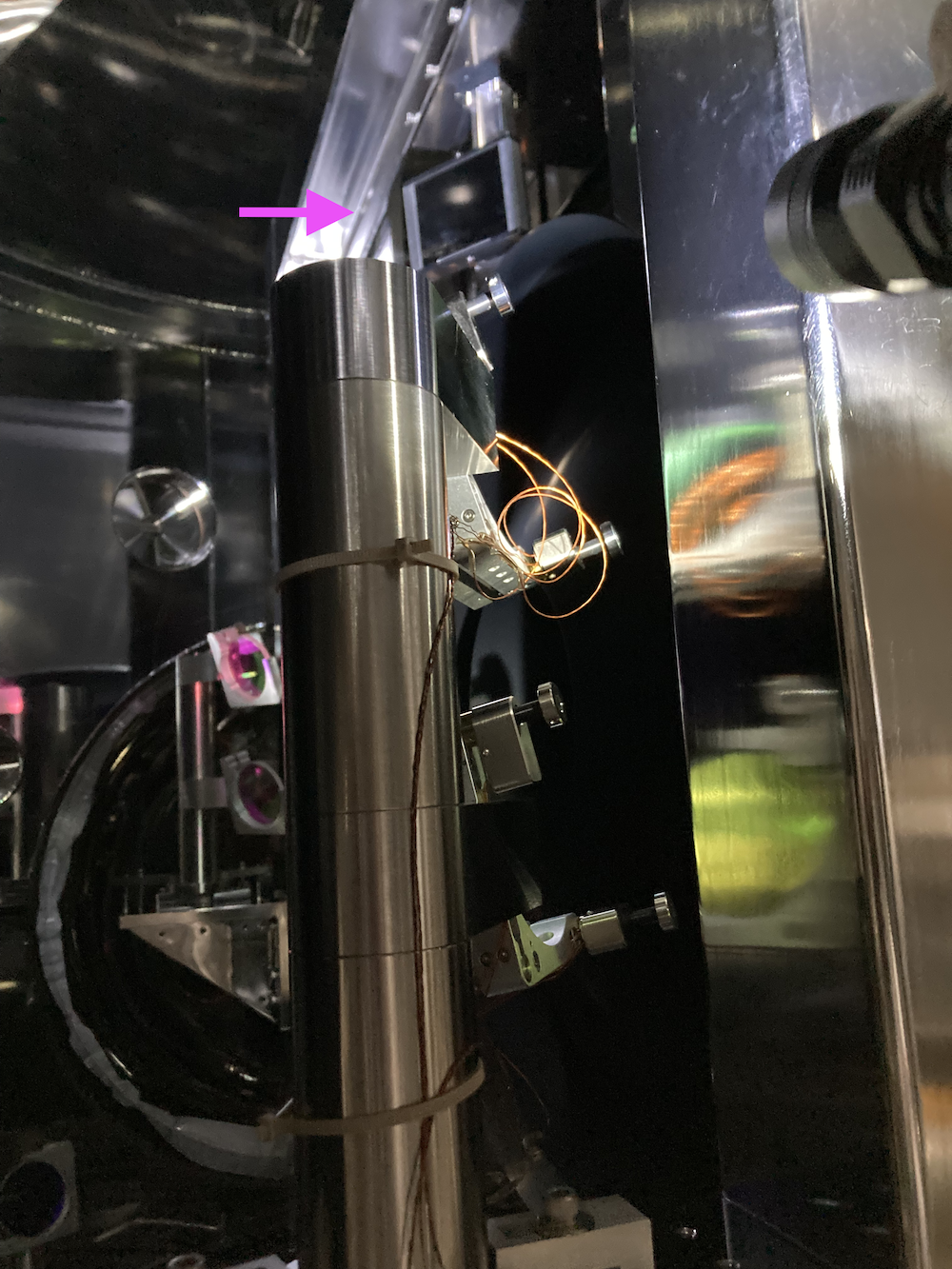
- We checked the mirror in the EYA chamber, which reflects the incident light from the ETMY to the telescope (Fig4). We saw something like white dust on the surface of the mirror. We think this could be a cause of the problem with the ETMY images, which causes the scattering on the ETMY image.
- Concerns
- Is it possible to clean the mirror in EYA in a safe way?
- GreenY is needed to see if the problem has been solved after the cleaning. Is it possible for the schedule?


[Yokozawa, Yuzu]
As an irregular maintenance of TCam for ETMX, we performed the visual inspection this morning. From our inspections, the TCam of ETMX was no problem, except for the small dust.
- During O4a and the commissioning period, the TCam for ETMX showed no troubles. The purpose was to see the TCam in good condition for comparison with the TCam for ETMY in the afternoon.
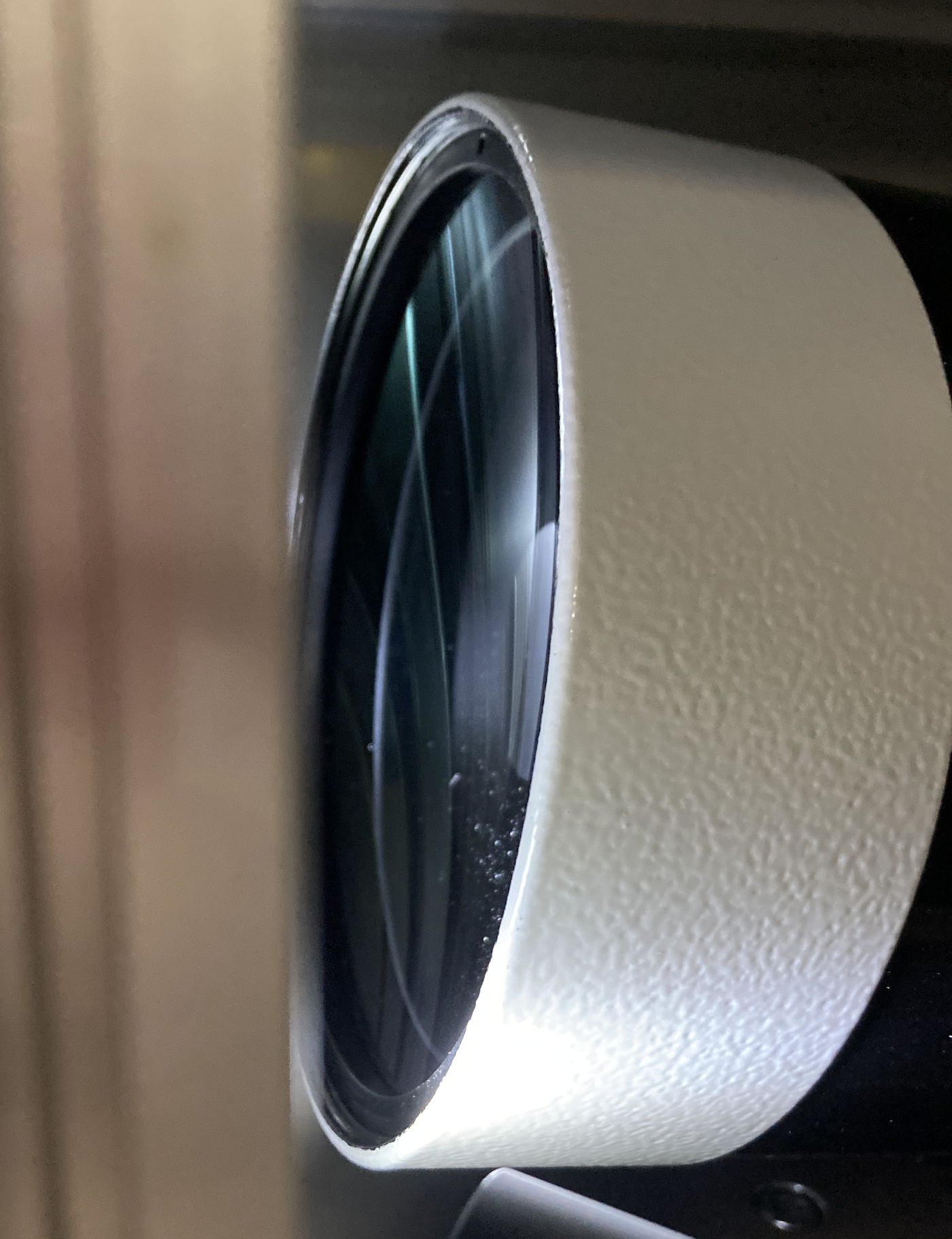
- We opened the one wall of the TCam (Fig1) and checked the surface of the objective lens. A little dust seemed to be on the surface (Fig2) (Fig3). Next time, we will try to clean it by using an air duster.
- We checked the mirror in the EXA chamber, which reflects the incident light from the ETMX to the telescope (Fig4). The photo shows a cloudy mirror, but this is due to poor camera performance... Eye inspection did not reveal any problems.


I analyzed the taken images and summarized the details in the wiki page(https://dac.icrr.u-tokyo.ac.jp/KAGRA/DAWG/Detchar/klog/klog28571).
Brief report
After I manipulated two images taken by two kinds of cameras, I overlayed two images. I have attached that image. It seems that the center of the images is different. I will investigate the cause deeper next time.

[Yamamura, Yuzu]
This is a report of Friday's activity.
In the past test (klog#28486), I found that the center of images taken by two kinds of cameras (ASI and gige) are different (see Fig) when we took the images with the two cameras and the beam slitter. There are two possibilities of the cause
- The location of the image sensor installed in the camera is not well centered for the incident light
- The BS was not positioned perpendicular to the incident light
To test these hypotheses, we took the several images with several condition. The analysis report will be summarized in DAC wiki.
I analyzed the taken images and summarized the details in the wiki page(https://dac.icrr.u-tokyo.ac.jp/KAGRA/DAWG/Detchar/klog/klog28571).
Brief report
After I manipulated two images taken by two kinds of cameras, I overlayed two images. I have attached that image. It seems that the center of the images is different. I will investigate the cause deeper next time.
[Ikeda, Yuzu]
We discussed this result. In our consideration, the reason why the image was off-center was that the camera adaptor for the ASI camera was not held tightly in place. Perhaps a shift of the image sensor is an incorrect extrapolation. I will reconsider the setup for the TCam test bench.
- In the four corners of the image taken by the gige camera, there are vignetting (in Japanese, called Kerare) (Fig1). The area size of these Kerare looks almost same size. So, the sensor of the gige camera should be no problem. So, we doubted something happened in the ASI camera side.
- Fig2 shows the adapter to hold the ASI camera (left black one). Right red one is the ASI camera. This adapter can be loose in some cases.
- Fig3 shows the inner part of the adapter. Two screws tighten the camera. As seen in this figure, when I tighteded only one screw, the camera will be shifted to one way. We suspenct this happened in the previous operation test. In quick calculation, the 0.5 mm off-center of the image sensor can explain the previous off-centered images. I will reconsider the setup for the TCam test bench.
- Note that from the visual inspection by Ikeda-san, the image sensor of the ASI camera is well centered in the camera. The 0.5 mm shift of the image sensor was not obserbed.
I attach the error message from Uchikata-san.
We confirmed that the science segment information is available on DQSEGDB and the information is correct. I suspect the temporal network error between the system-B and the DQSEGDB.
[Narikawa, Uchikata, Yokozawa, Yuzur]
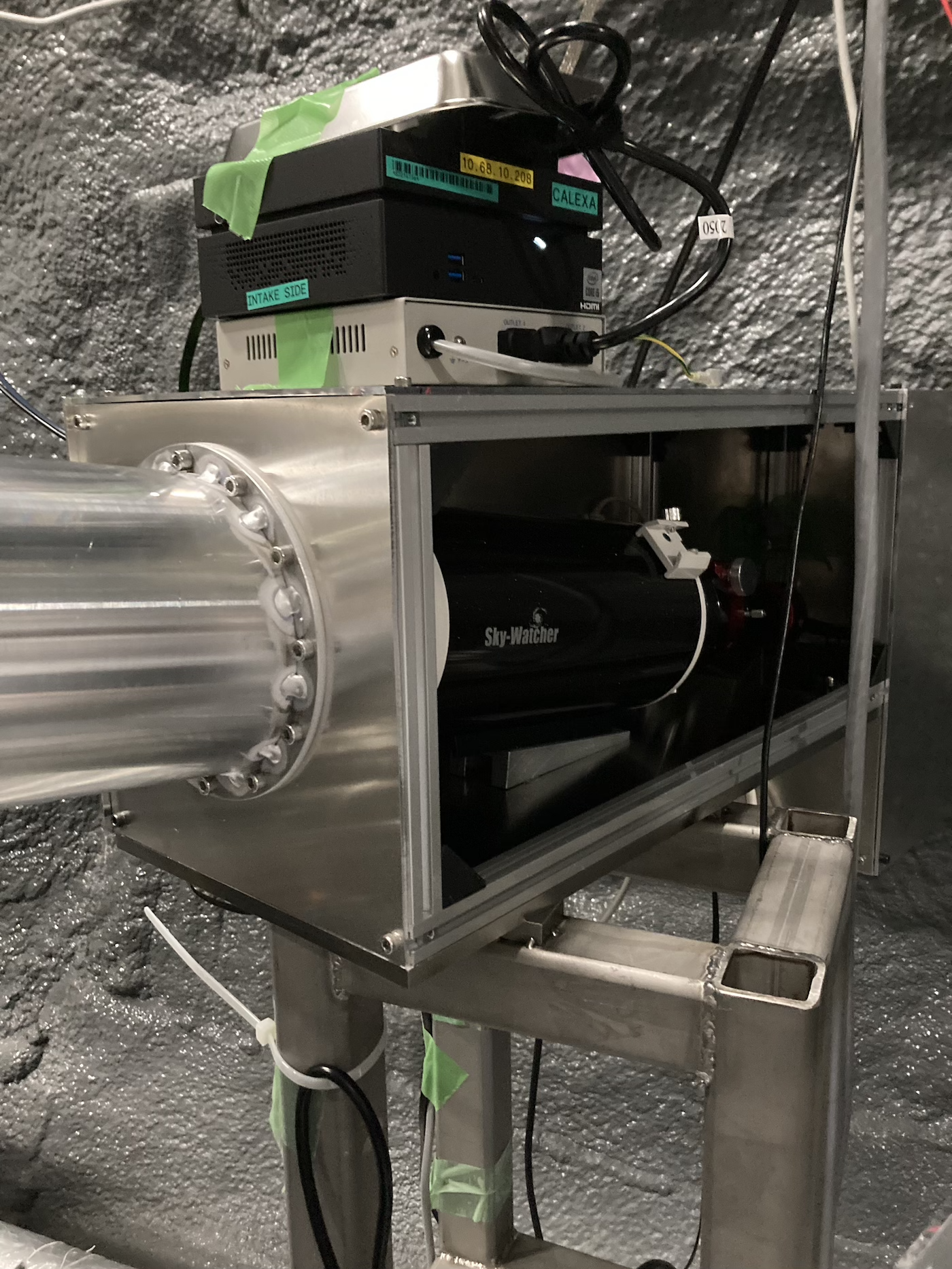
We carried the TCam testbench (the telescope, tripod, and ASI camera) into the mine and performed the operation test by combining the new BS and gige camera. The new system works well to take images. But, I found several new issues...
- The setup of the BS, gige camera, manual focuser, and ASI camera can be seen in [Fig1] [Fig2].
- I was able to get good focus with the ASI camera alone, and the same with the gige camera alone. However, I could not find a good focus for both cameras at the same time, as shown in Fig3 and Fig4. I need to consider the setup again.
- Fig3 shows another issue. The centers of the images shown by the red and white crosshairs are different for the images. This may be caused by the BS not being properly placed at a 90 degree angle to the incident light; the light split by the BS is not traveling straight to the gige camera, so the center of the image is different.
- Using the gige camera application, I could not take the image in the PNG format. I could take the image in TIFF format.


[Ikeda, Oshino, Yuzu]
We prepared the operation test of the new gige camera for the future upgrade of the TCam, at Hokubu Kaikan. After several attempts, I succeeded in taking the image with a gige camera.
- We set the IP address (192.168.3.3 and 192.168.3.2) for the gige camera and the Mac. The server for the gige camera is under setting by Ikeda-san and Oshino-san. Instead, I used the Pylon Viewer, which BASLER provided.
- After connecting the gige camera and Mac, I needed to wait for 30 seconds or so.
- At first, the image is contaminated by the horizontal black pattern due to the limitation of the communication speed. I changed the parameter (Transport Layer Cintrol -> GigE Vision -> Inter-Packet Delay) to be 65536. That pattern disappeared, though sometimes it appeared.
- The camera's image sensor is dirty (see the attached image). I will clean it.
- Although I tried to take the image with good focus, it failed. I will check the options and parameters on the camera application.
- In 20 minutes, the connection between Mac and the gige camera was lost for some reason. I'm doubting the effect of the heat.


While cleaning the second floor of BS, we noticed some heavy components were placed on the floor. I wondered if these could fall and damage the experimental equipment downstairs or injure the researchers.
Also, the stepladder on the second floor of PR2 was not secured to the frame. Is this ok for the safety rule? For details, please check the images.


![[before the cleaning]](https://klog.icrr.u-tokyo.ac.jp/osl/uploads/29414_1715068196_IMG_3745.jpg)
![[after the cleaning]](https://klog.icrr.u-tokyo.ac.jp/osl/uploads/29414_1715068200_IMG_3747.jpg)
![[4/1]](https://gwdet.icrr.u-tokyo.ac.jp/~controls/capture/tcam/ITMX_fit/2024/0401/TCam_ITMX_00111_2024_0401_174704_fit.png)
![[4/26]](https://gwdet.icrr.u-tokyo.ac.jp/~controls/capture/tcam/ITMX_fit/2024/0426/TCam_ITMX_00011_2024_0426_081020_fit.png)
![[fig]](https://klog.icrr.u-tokyo.ac.jp/osl/uploads/28830_1710317728_IMG_3033.png)
![[fig]](https://klog.icrr.u-tokyo.ac.jp/osl/uploads/28830_1710317799_IMG_3036.png)
![[fig]](https://klog.icrr.u-tokyo.ac.jp/osl/uploads/28830_1710317866_IMG_3040.JPG)
![[ETMX]](https://gwdet.icrr.u-tokyo.ac.jp/~controls/capture/tcam/ETMX/2024/0313/TCam_ETMX_00000_2024_0313_113048.png)
![[ITMX]](https://gwdet.icrr.u-tokyo.ac.jp/~controls/capture/tcam/ITMX/2024/0313/TCam_ITMX_00000_2024_0313_125427.png)
![[11:18~11:23]](https://klog.icrr.u-tokyo.ac.jp/osl/uploads/28821_1710227764_IMG_4802.jpg)
![[11:23~]](https://klog.icrr.u-tokyo.ac.jp/osl/uploads/28821_1710227828_IMG_4803.jpg)
![[Fig]](https://klog.icrr.u-tokyo.ac.jp/osl/uploads/28821_1710227893_IMG_4804.jpg)
![[Example]](https://klog.icrr.u-tokyo.ac.jp/osl/uploads/28821_1710231453_TCam_ITMX_00011_2023_1228_073737.png)
![[Fig3]](https://klog.icrr.u-tokyo.ac.jp/osl/uploads/28812_1710156341_IMG_3020.png)
![[Fig4]](https://klog.icrr.u-tokyo.ac.jp/osl/uploads/28812_1710156453_IMG_3021.png)
![[example]](https://gwdet.icrr.u-tokyo.ac.jp/~controls/capture/tcam/ITMX/2024/0308/TCam_ITMX_00001_2024_0308_112651.png)
![[example]](https://gwdet.icrr.u-tokyo.ac.jp/~controls/capture/tcam/ITMX/2024/0308/TCam_ITMX_00001_2024_0308_113357.png)
![[Figure of ETMY]](https://gwdet.icrr.u-tokyo.ac.jp/~controls/capture/tcam/ETMY/2022/0425/TCam_ETMY_01110_2022_0425_141555.png)
![[Fig1]](https://klog.icrr.u-tokyo.ac.jp/osl/uploads/28486_1706776140_20240201%20104805.JPG)
![[Fig2]](https://klog.icrr.u-tokyo.ac.jp/osl/uploads/28486_1706776092_IMG_2406.JPG)